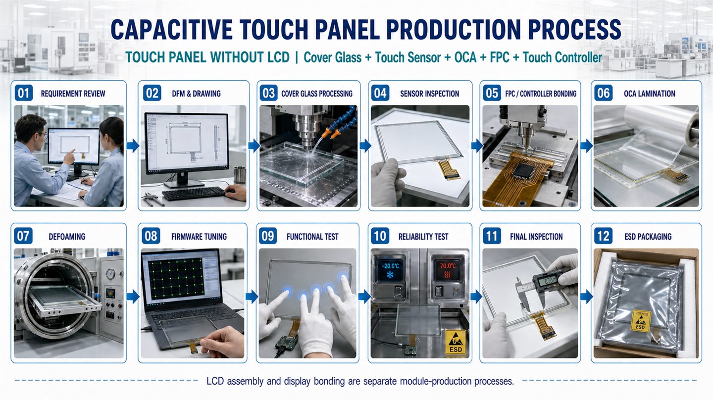
01. Requirement Review
Each ODM/OEM project begins with a review of the equipment structure, operating environment and required service life.
- Housing opening, compression tolerance and clamping pressure
- Cover-glass outline, thickness and visible area
- FPC position, length and bending direction
- USB or I²C interface and operating system
- Temperature, glove, water and EMC/ESD requirements
- Transmittance, haze and reflectance requirements
- Abrasion life and chemical-resistance requirements
- Customer-supplied and Ever Glory-supplied components
Customers are encouraged to provide a housing 3D model so that mechanical stress, FPC bending and installation risks can be evaluated before sample production.
02. DFM and Drawing Confirmation
The DFM review covers the cover-glass outline, sensor active area, FPC routing, connector position, touch controller, grounding, shielding, OCA specification and installation clearance.
A tolerance matrix can be prepared for critical dimensions. Where applicable, a DFM risk memorandum identifies minimum printed-border width, FPC bending radius, OCA edge allowance, hole-to-edge distance and tolerance-accumulation risks.
Prototype approval does not automatically represent volume-production approval. A separate production-readiness review is recommended before mass production.
03. Cover Glass Processing
The cover glass is processed according to the approved drawing through cutting, CNC profiling, drilling, edge grinding, strengthening, printing and surface treatment.
For strengthened glass, surface-compressive stress and depth-of-layer requirements can be defined in the inspection plan. Printed glass can undergo first-article adhesion and solvent-resistance verification.
AG, AR and AF treatments must specify the treated surface. Haze, reflectance, transmittance and abrasion-life requirements are confirmed according to the application.
04. Capacitive Touch Sensor Inspection
The capacitive touch sensor is inspected for dimensions, active-area position, ITO continuity, channel resistance, electrode uniformity, surface appearance and FPC bonding position.
For projects exposed to humidity or elevated processing temperatures, environmental preconditioning or impedance-drift sampling can be included in the quality plan.
Sensor materials are controlled through defined storage temperature, humidity, packaging and shelf-life requirements. The sensor detects touch input and does not contain an LCD.
05. FPC and Touch Controller Bonding
The FPC is aligned and bonded to the touch sensor. Depending on the design, the touch controller can use a COB or COF structure.
ACF bonding temperature, pressure, time, bonding-head flatness and alignment are controlled through the applicable work instruction and production records.
Post-bonding inspection covers bond strength, circuit continuity, channel resistance and controller communication. First-article testing can simulate the actual FPC bending direction. Conformal coating for COB structures can be evaluated for humid or contamination-prone environments.
06. OCA Lamination
The cover glass and touch sensor are cleaned, aligned and laminated with optical clear adhesive. Where required, plasma treatment can be evaluated to improve surface cleanliness and adhesion.
The approved OCA manufacturer, model and thickness are recorded in the BOM. Substitutions require engineering review because adhesive properties can affect sensitivity, glove operation, optical appearance and environmental reliability.
Lamination controls include environmental cleanliness, temperature, humidity, alignment, particle control, pressure and edge allowance.
07. Defoaming
After lamination, the touch panel undergoes a controlled defoaming process. Temperature, pressure and processing time are defined according to the cover-glass structure and OCA specification.
The assembly is inspected for bubbles, foreign particles, adhesive overflow, delamination, alignment deviation and Newton rings.
The appearance standard should define the inspection distance, lighting and viewing angle, including the acceptance boundary for Newton rings visible only under strong oblique lighting.
08. Touch Firmware Tuning
Touch firmware is tuned for sensitivity, coordinate accuracy, edge response, multi-touch, glove operation, water rejection, palm suppression and noise filtering.
Bench tuning is the standard initial environment. Equipment-level EMI optimization requires the customer to provide a complete device or representative electrical setup.
Each approved configuration is controlled by firmware version, parameter-file version, hardware revision and release record. Firmware changes are followed by regression testing of all applicable touch functions.
09. Functional Testing
Each touch panel is checked for USB or I²C communication, controller identification, coordinate accuracy, multi-touch response, linearity, edge operation, dead zones and unintended touch events.
The test plan defines the number and location of test points, including corners, edges and the center active area.
For wide-temperature projects, real-time touch monitoring can be performed at specified high and low temperatures. Compatibility can be evaluated for Windows, Linux, Android and selected embedded systems.
10. Reliability Verification
Available verification can include temperature operation and storage, temperature cycling, humidity storage, FPC bending, connector retention, glass impact, printing adhesion, abrasion, water resistance and chemical resistance.
ESD verification defines contact discharge, air discharge, discharge locations, powered condition and functional recovery requirements.
Prototype qualification is separated from volume-production sampling. For medical equipment applications, verification applies only to the touch component and does not represent certification of the complete medical device.
11. Final Inspection and Traceability
Final inspection covers dimensions, visible and active areas, FPC position, connector specification, printing, scratches, chips, bubbles, particles and touch functionality.
The appearance standard defines inspection distance, lighting, viewing angle, background and allowable defect size. Critical electrical parameters can be sampled according to the production control plan.
Where required, traceability can link the finished touch panel to cover-glass, sensor, OCA, FPC, controller and bonding lots, firmware version and inspection records.
12. ESD- and Moisture-Protective Packaging
Approved touch panels are packaged to reduce scratching, contamination, electrostatic discharge, moisture exposure and FPC damage.
Packaging can include surface protection film, ESD bags, moisture-barrier materials, project-specified desiccant, humidity indicators, protective trays and lot identification.
FPCs are secured within the approved bending direction and radius to prevent repeated movement during vibration and transportation.