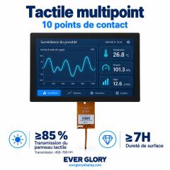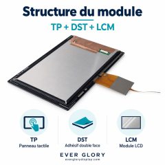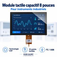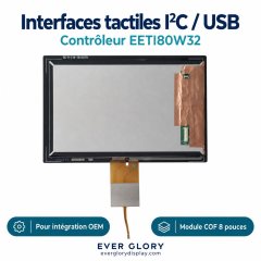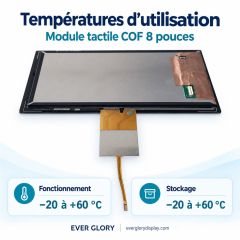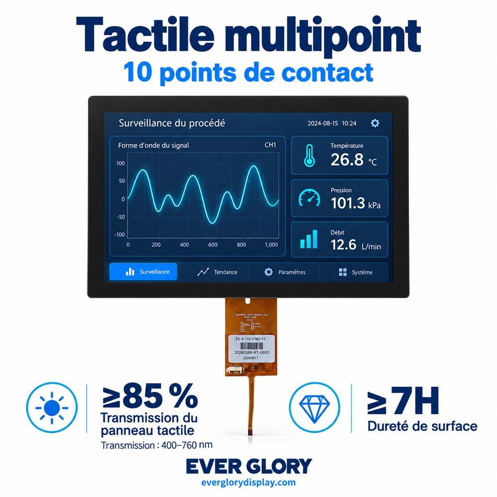
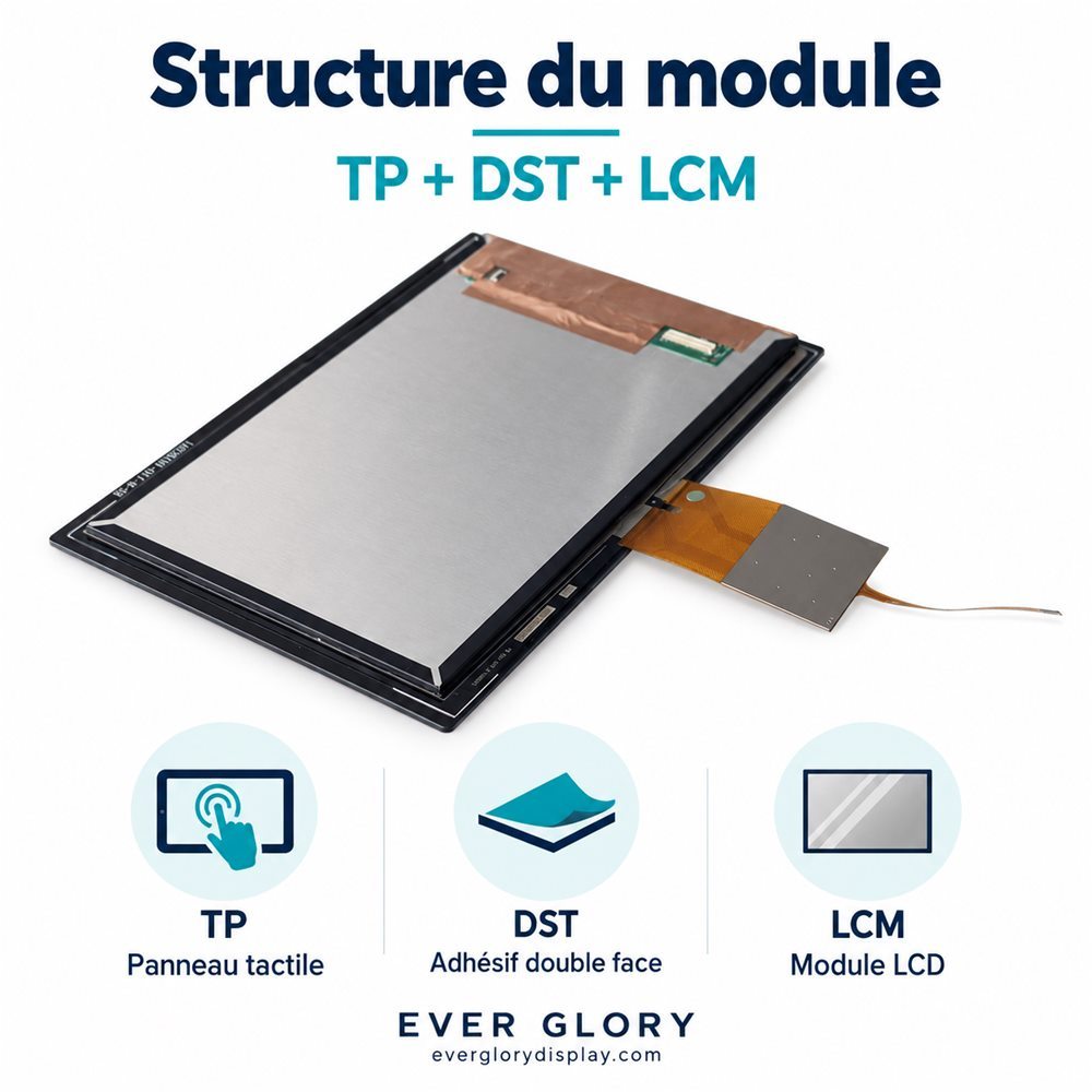
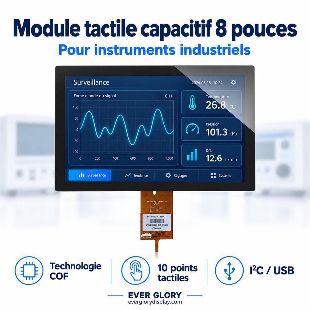
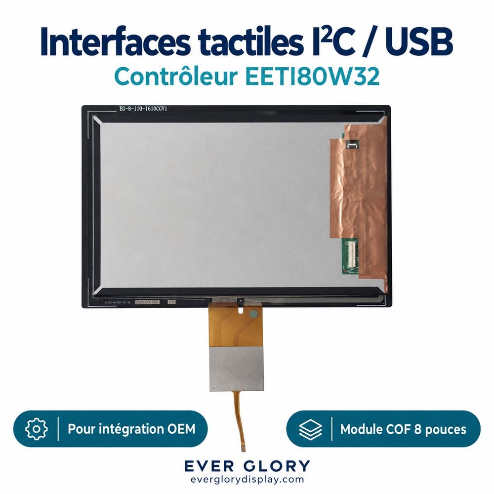
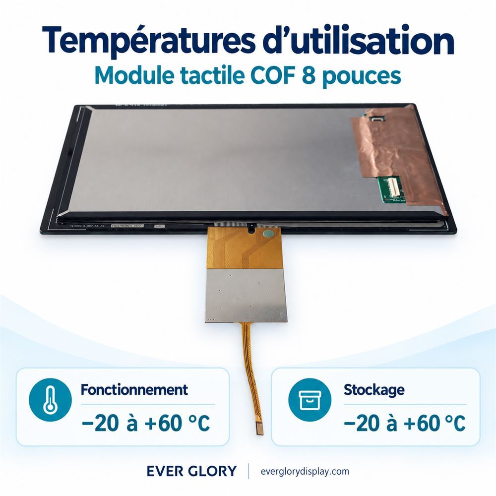
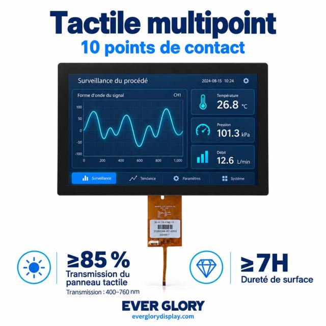
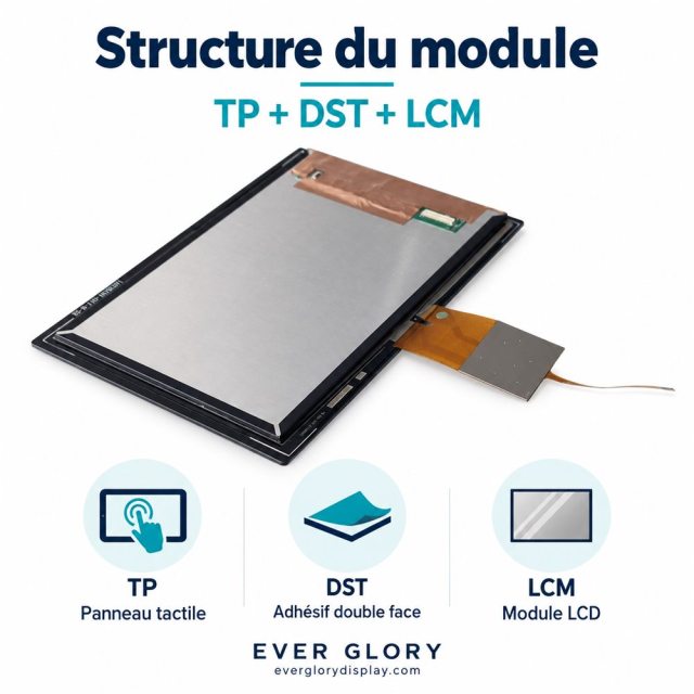
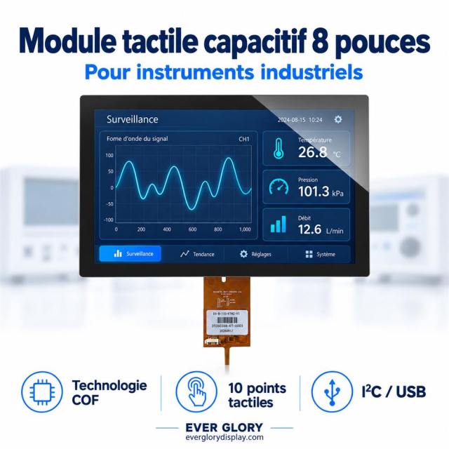
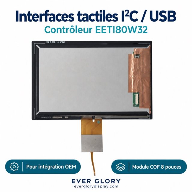
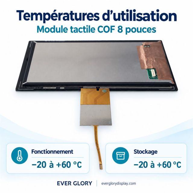
The EG-8-110-COF53-KT is an 8-inch capacitive touch module for instruments and measurement devices in industrial use. A projected capacitive touch panel — its controller mounted chip-on-film — sits over an 8-inch LCD, and the two are held together by a double-sided adhesive layer, which is exactly what the TP + DST + LCM designation on the drawing describes. The touch side runs on an EETI80W32 controller with 10-point reporting and an I²C touch interface or USB connection, the front is specified at ≥7H surface hardness with ≥85% panel transmission across 400–760 nm, and operating and storage temperatures are both rated −20 to +60 °C.
What arrives is a matched front-end assembly, not a finished monitor. Data acquisition, signal processing and the graphical interface stay in your own electronics and software; we supply the touch panel, the LCD and the touch controller as one unit with a defined outline, defined mounting areas and a flex tail at a fixed exit position. That is the arrangement instrument makers ask for when the display has to be designed into their own housing rather than bolted on as an external screen.
Because the stack is bonded rather than clamped, the mechanical design has to respect the adhesive band and the flex path. The sections below cover the structure, the touch interfaces, the optical figures and the supports settle before the enclosure drawing is released. LCD resolution, luminance and video interface are not part of the touch specification; they are confirmed from the LCD datasheet for the configuration you order.
The three letters name the three elements you are designing around: TP is the projected capacitive touch panel, DST is the double-sided adhesive layer that joins it, and LCM is the LCD module underneath. In practice the touch panel is held to the LCD by a tape layer around the perimeter of the assembly, shown in our layer view along with the black bezel around the active area and the flex tail leaving the bottom edge; that tail is the route by which the I²C touch interface or USB connection leaves the assembly.
That construction is a mechanical bond, not an optical one. The touch panel and the LCD are not fused with optical glue, so there is a bonded interface between them rather than a single continuous optical path. If your requirement assumes full optical bonding, that is a different build and its feasibility is examined project by project — it should not be read into this specification.
The mechanical consequences are the ones that decide whether the housing works. The adhesive band defines where the assembly may be supported: screws, clips and gaskets should press on the housing or on a frame, never on the bonded border, because a clamp squeezing the adhesive line shows up later as a dead zone at the edge of the touch area. Peripheral clearance has to be planned around the whole stack, and because the display outline and the cover glass outline are not the same dimensions, both belong in your mechanical model.
One more point for service planning: a bonded module is not a field-separable assembly. If the front is damaged in service, the module is replaced as a unit rather than re-glassed on site, so it is worth deciding early how many spares your service organisation wants to hold.
Two figures describe the front, and both belong to the touch panel rather than to the LCD behind it. Transmission is specified at ≥85% across the visible range of 400–760 nm, and surface hardness is stated at ≥7H.
The transmission figure is the proportion of light the touch panel lets through across that band. It is not a luminance measurement of the assembled module and it does not tell you how bright the finished front will look. The practical reading is the other way round: whatever LCD you pair with this touch module for instruments, roughly the panel's own loss has to be subtracted before you decide the screen is bright enough for the place it will stand. Choose the LCD brightness with that loss already accounted for, not after the prototype is criticised for looking dim.
The hardness figure is a pencil-hardness value for light surface scratching. It is not an impact rating, it is not a chemical-resistance classification, and on its own it does not qualify the front for repeated cleaning with aggressive agents. If your instrument is wiped down on a schedule — with an alcohol-based cleaner, a solvent, or an abrasive cloth — write the agent, the cloth and the frequency into the requirement so the cleaning routine can be assessed rather than assumed. In everyday use, a soft cloth and a mild cleaner keep the front clean without working against a coating or the bonded edge.
One design point that pairs with both figures: dust and grit trapped at the bezel edge act as an abrasive every time something wipes across the glass, so a bezel that sits slightly proud of the front does more for long-term appearance than any surface specification.
Référence EG-8-110-COF53-KT : module d'affichage 8 pouces avec tactile capacitif COF, de structure TP + DST + LCM, équipé du contrôleur tactile EETI80W32. Température de fonctionnement et température de stockage : −20 à +60 °C. Matériaux conformes aux exigences RoHS selon la spécification fournie. La résolution, la luminance et l'interface vidéo du LCD sont à confirmer dans la fiche LCD de la configuration retenue, avant le choix de la carte hôte.
| Reference | EG-8-110-COF53-KT |
| Product type | 8-inch capacitive touch module with COF touch panel |
| Diagonal | 8 inch |
| Primary application | Industrial instruments and measurement devices |
| Structure | TP + DST + LCM |
| Assembly | Double-sided adhesive (DST) bonding |
| Touch controller | EETI80W32 |
| Touch interfaces | I²C / USB; connection configuration to be confirmed |
| Touch points | 10 |
| Touch panel transmission | ≥85% across 400–760 nm |
| Surface hardness | ≥7H |
| Operating temperature | −20 to +60 °C |
| Storage temperature | −20 to +60 °C |
| Materials | RoHS-compliant per the supplied specification |
La documentation indique I²C/USB comme interfaces de communication tactile. Le raccordement retenu, le brochage et les éventuels adaptateurs doivent être confirmés pour la configuration commandée. La compatibilité avec votre carte hôte dépend également de l'alimentation, des niveaux logiques, du protocole et du support logiciel. L'indication I²C/USB concerne le tactile : elle ne définit pas l'interface vidéo du LCD.
La transmission du panneau tactile est spécifiée à ≥85 % sur la plage visible de 400 à 760 nm. Cette valeur concerne le panneau tactile et ne correspond pas à une mesure de luminance du module LCD assemblé. La dureté de surface annoncée est ≥7H. Elle ne constitue pas, à elle seule, une qualification de résistance aux chocs, aux produits chimiques ou aux nettoyages répétés. Les produits d'entretien et les conditions d'essuyage doivent être précisés si ces usages font partie du cahier des charges.
Pour sélectionner cet écran tactile capacitif 8 pouces, commencez par vérifier les exigences d'affichage et la compatibilité avec votre électronique. La résolution, la luminance, les angles de vision et l'interface vidéo du LCD doivent être confirmés avant la validation de la carte hôte. Prévoyez ensuite une vérification sur l'équipement réel : fixation, passage du FPC, mise à la terre, stabilité de l'alimentation et fonctionnement tactile à proximité des circuits de mesure. Les essais doivent correspondre aux conditions d'utilisation de votre instrument. Pour examiner les adaptations mécaniques et électriques possibles, consultez notre service de personnalisation OEM/ODM en précisant votre application.
Le module comprend-il le LCD, le tactile et le contrôleur ? La configuration présentée associe un panneau tactile capacitif COF et un LCD selon la structure TP + DST + LCM ; le contrôleur tactile indiqué est EETI80W32. Le périmètre de livraison des câbles, des connecteurs et des éventuelles cartes d'adaptation doit être précisé dans le devis et la nomenclature approuvée. Pour le raccordement du tactile en I²C ou en USB à votre carte hôte, la documentation mentionne I²C/USB ; avant le raccordement, il faut confirmer l'interface retenue, son brochage, l'alimentation, les niveaux logiques et le support logiciel. La présence des deux mentions ne signifie pas automatiquement que les deux interfaces sont disponibles sur la configuration commandée.
Transmettez l'application visée, les plans du boîtier, les caractéristiques de votre carte hôte et les performances d'affichage recherchées. Indiquez également les quantités prévues, le calendrier du projet et les contraintes particulières de température, de nettoyage ou d'environnement électrique. Contactez Ever Glory pour une étude d'intégration et un devis adapté à votre instrument industriel.
Le format 8 pouces permet de concevoir une interface présentant des valeurs mesurées, des courbes, des paramètres de réglage et des messages d'état. Il peut être étudié pour des appareils de mesure, des instruments de laboratoire industriel ou des équipements de surveillance de procédés, selon les exigences de chaque projet. Les écrans de surveillance illustrés sur les images sont des exemples d'application. L'acquisition des données, leur traitement et l'interface graphique sont assurés par l'électronique et le logiciel de l'équipement hôte.
La configuration COF intègre le circuit de commande tactile sur un support flexible. L'intégration mécanique doit tenir compte de l'espace disponible pour le FPC, de son cheminement et de la protection des composants qu'il porte. Avant de figer le boîtier, vérifiez les dimensions du module complet, les zones de fixation, la longueur du FPC, la position de sortie et les contraintes de flexion indiquées sur les plans. Les dimensions de l'affichage et celles du verre de protection doivent être distinguées.
Choosing the right touch module for a new enclosure is usually a joint exercise, so our engineers work directly with your design team from the first drawing. Send us your mechanical outline, interface and operating environment and we will match a configuration from our range, confirm tolerances and share drawings for review before tooling. When something behaves unexpectedly in the field, we help trace it — controller settings, calibration, sealing or assembly — and give installation and start-up guidance. With 15 years in the touch industry and our manufacturing base in Dongguan, support stays with the people who build the part.
Yes. The delivered assembly combines a COF capacitive touch panel, an 8-inch LCD and the touch controller in the TP + DST + LCM structure. Cables, connectors and any adapter board are a separate line: they are listed in the quotation and the approved bill of materials, so check that list rather than assuming a cable assembly is included.
Both are named for the touch channel, and the configuration you order ships one wiring arrangement. Before anything is wired, confirm which interface is used, its pinout, the supply it expects and the logic levels, then check driver support on your host system. Seeing both names in a specification does not mean both are active at once or that neither needs an adapter.
Those values live in the LCD datasheet for the configuration you order, not in the touch specification. Resolution and luminance define your layout and the front-of-screen brightness; the video interface has to be fixed before the host board is designed. The I²C and USB note describes the touch channel only and says nothing about how video reaches the LCD, so ask for the LCD sheet when you request the assembly drawing.
Treat the flex as a part with a defined route. Keep the length and bend radius from the drawing, avoid any pull on the bond at the panel edge, and leave clearance for the components carried on the film. The exit position is fixed by the module, so the housing cut-out and the internal routing are designed around it — not the other way round.
No. The structure is TP + DST + LCM, so the touch panel and the LCD are joined with a double-sided adhesive layer. Full optical bonding with OCR or OCA is a different construction; if your application needs it, the feasibility is reviewed for the individual project rather than assumed from this specification.
That is confirmed on your instrument, not from a datasheet. Grounding strategy, cable routing, supply stability and the proximity of switching regulators or a measurement front end all affect a capacitive sensor. Put the module in the real housing with the real wiring and run the touch tests at the temperatures and interference conditions your equipment meets; if something looks marginal, our engineers can review the layout with you.
Neither is confirmed for this reference. If operators wear gloves, tell us the material and thickness; if the front gets wet, describe how much water and how often. A capacitive front can be configured and tested for those conditions, but the answer depends on the glove and on the water, so it is settled by a test rather than a general statement.
Operating and storage are both rated −20 to +60 °C. That is an ambient rating, not a continuous-duty qualification: daily run time, the internal temperature of your housing and the backlight lifetime all need checking for your instrument, particularly if the enclosure is sealed or the display sits close to a heated front panel.
Send the application, the housing drawings and the host board details, and sampling and documents can be defined for the project: LCD datasheet, touch specification, assembly drawing and interface definition. Ask your sales contact about sample availability and which documents are ready for the configuration you are considering; order quantities, lead times and warranty terms are set out in the commercial offer.
Adaptations are examined per project. Mechanical changes to the outline or the flex position and electrical changes to the interface are assessed against your drawings and your schedule rather than offered as catalogue options. Send the housing drawing and the host board characteristics with the enquiry and the OEM touch display module can be reviewed against them.