Product Overview
This 10.1 inch sunlight viewable display capacitive touch module is made for front panels that stand in daylight all day: outdoor control cabinets, wayside and transport equipment, gate and access-control terminals, and outdoor instrument housings where an indoor-grade display would wash out by mid-morning. The touch sensor and the cover glass form a G+G structure, and the whole stack is joined with a full optical bond, so the image sits directly behind the front surface instead of behind an air gap.
Each OEM touch module arrives as one assembled part rather than a panel to be bonded on site. Product number EG-10.1-A-1610V1-KTCTP-T covers the complete display module: touch panel, bonded display and a single ribbon tail to route into your control board.
Two things decide whether an outdoor interface is usable, and this module is built around both. The first is what the screen looks like with the sun on it. The second is whether a finger still lands where the user aimed after the enclosure has been sitting in heat for a few hours. The sections below work through the optical and thermal design, the dimensions your front-panel opening needs, the installation sequence, and the details worth confirming before you place an order.
Specifications
| Product number |
EG-10.1-A-1610V1-KTCTP-T |
| Touch panel P/N |
EG-10.1-A-1610V1 |
| Touch structure |
G+G glass with optical bonding |
| Cover outline dimension |
246.96 × 165.6 mm |
| Touch panel view area |
216.96 × 135.6 mm |
| Touch panel active area |
217.96 × 136.6 mm |
| Touch panel thickness |
2.75 mm |
| Display outline dimension |
213.22 × 150.6 mm |
| Display active area |
216.96 × 135.6 mm |
| Display thickness |
4.4 mm |
| Impact resistance |
≥IK07 |
Sunlight Readability and Thermal Stability
- A temperature-stable ITO sensor. The 10.1 inch touch module uses a high-temperature-resistant, low-resistance ITO coating whose resistivity barely moves between 60 °C and 70 °C. Correcting drift in the sensor material itself is more dependable than compensating for it afterwards in software.
- Controller-level compensation. The touch IC is specified across the full working temperature range and runs real-time baseline calibration at high temperature, together with ITO resistance temperature-coefficient compensation. That is what pulls offset and jumping touch points back into line as the enclosure warms through the morning.
- A bonded stack that sheds heat. The G+G structure is fully optically bonded, which removes the air layer that would otherwise trap heat between the touch panel and the display; the design also reserves heat-dissipation paths and keeps the module clear of internal heat sources inside the housing, which lowers surface temperature and limits thermal deformation of the ITO.
- Calibration at three temperatures. Each unit is calibrated at room temperature, at 60 °C and at 70 °C and carries several parameter sets that switch automatically to match the working condition. Touch stays accurate in afternoon heat without anyone adjusting settings on site.
- Readability from the same stack. Because the layers inside the module are bonded rather than stacked with an air gap, the double reflection that turns an unbonded panel into a mirror in direct sun does not occur, and the cover glass carries an anti-reflection layer. Contrast holds, so the display does not have to be driven at maximum brightness just to be legible.
Long-Term Sun Exposure Durability
- Low-iron tempered cover glass. Ultra-clear high-alumina silicon glass with a low-iron formula is naturally UV-resistant: it resists yellowing under long exposure and holds its light transmission instead of turning milky over the years.
- UV-blocking AR and AF coatings. The cover surface carries a UV-resistant anti-reflection film plus an anti-fouling finish. The AR layer screens ultraviolet before it reaches the sensing and bonding layers, while the AF finish lets a soft cloth lift dust and fingerprints without abrasives.
- Weather-resistant bezel ink. The printed border uses an outdoor-grade UV-curable ink with strong adhesion and high/low-temperature cycle resistance, so it does not crack, peel or fade at the edge of the glass after season upon season of exposure.
- UV-resistant adhesive and edge seal. The optical adhesive and the waterproof sealant around the perimeter stop ultraviolet creeping in from the sides, protecting the bond line and the circuits, which is where ageing usually starts on an outdoor panel.
- What this means in service. Sun damage rarely shows up as a sudden failure; it appears as a slow colour shift and a dull front. These four layers are chosen so the glass face is not the part that limits how long the equipment can stay outdoors.
Enclosure Fit and Dimensions
Start with the front-panel opening. Of the three outlines in the drawing, the cover is the largest and the display the smallest, so the glass runs roughly 34 mm wider and 15 mm taller than the display beneath it. That margin is the landing area — the flat band your bezel or gasket presses onto — and in practice it leaves around 17 mm of glass on each side and 7.5 mm at the top and bottom for a seal or clamp.
The viewing window has to sit inside the touch panel's view area, which matches the display's active area exactly, so no strip of the picture is ever hidden behind the frame. The touch panel's active area is 1 mm larger in both dimensions than that window, which means a finger landing a fraction outside the visible image still registers on the sensor.
Stack height is worth planning early, because the 10.1 inch sunlight viewable display capacitive touch module adds 2.75 mm of touch panel and 4.4 mm of display before any adhesive or gasket compression. The front is tempered glass, so a bumped tool or a trolley clipping the panel is less likely to chip it than a plastic or film front, but the mounting should never put bending load across the glass — an even clamp around the border keeps the bonded stack flat and the touch response uniform.
If your opening is already cut and these proportions do not line up, send the front-panel drawing across. We will check it against the standard outline, and where the standard part will not fit, we can quote a custom touch module built to your aperture.
Installation and Commissioning
- Check the drawing against the metal. Lay the cover outline, the view window and the display outline over your front panel before anything is fastened; the glass-to-bezel landing is the dimension that causes trouble most often. If the opening is non-standard, this is also the point where a custom touch module is specified rather than a standard part.
- Seat the module under an even load. Compress the gasket uniformly around the border, keep the ribbon tail clear of sharp edges and moving parts, and leave the heat path behind the display open — the housing, not the module, decides how much heat stays inside.
- Wire the interface and earth the housing. Route the USB cable away from switching power lines and bond the enclosure to ground. Electrical noise is one of the conditions an outdoor cabinet has to live with, and good grounding costs nothing.
- Test the whole surface, not the centre. Run a touch test at the corners as well as the middle after assembly, then repeat it with the housing closed. A bezel that pinches the bonded G+G structure usually shows up as a dead band rather than a visible crack.
- Look at it in real daylight. Power the unit outdoors around midday and check the interface at reading distance and at an angle. If reflection is still heavy at your mounting angle, change the enclosure tilt before adding a second window in front of the glass — every extra layer costs contrast.
- Re-check after a thermal cycle. A day in the sun and a cool night is normally enough to reveal a mounting problem. Because an OEM touch module arrives calibrated across its working range, drift at this stage almost always traces back to the mounting or the grounding rather than to the panel.
Touch Performance and Controller
| Touch points |
10 points (typical) |
| Touch sensing |
Projected capacitive, finger contact (no pressure needed) |
| Controller interface |
USB |
| Controller supply voltage |
USB 5 V (typical) |
| Touch report rate |
≥100 Hz |
| Touch response time |
≤25 ms |
| Touch linearity |
±2 mm |
| Multi-touch handling |
Two-finger gestures and two-handed operation resolved by the host software from the reported touch points |
Ordering and Delivery
- Quote both numbers. The product number covers the bonded assembly and the touch panel P/N covers the panel inside it. Give us both when you enquire so the touch panel and the display stack are matched from the same build.
- Start from the drawing. Every OEM touch module order begins with the front-panel drawing. Ask for the current 2D drawing and the specification sheet for your project records, and confirm the tolerances before any metal is cut.
- Standard or custom. Tell us whether the standard outline fits an opening you already have, or whether the aperture, gasket type or mounting method calls for a custom touch module, and send the aperture dimensions with the enquiry.
- Samples and pre-production units. Ask your sales contact about sample availability and how pre-production units are scheduled — the answer depends on the configuration and the current build queue.
- Lead time, price and payment terms. These are quoted per order. Confirm them with your sales contact at the same time as the drawing and the quantity, since both affect the schedule.
- Packing and transport. Glass-fronted modules travel in protective packing. If your line needs a particular tray format or packing arrangement, say so with the order and we will confirm what is possible.
Technical Support & Model Matching
Choosing the right touch module for a new enclosure is usually a joint exercise, so our engineers work directly with your design team from the first drawing. Send us your mechanical outline, interface and operating environment and we will match a configuration from our range, confirm tolerances and share drawings for review before tooling. When something behaves unexpectedly in the field, we help trace it — controller settings, calibration, sealing or assembly — and give installation and start-up guidance. With 15 years in the touch industry and our manufacturing base in Dongguan, support stays with the people who build the part.
FAQ
Q1. What is the operating temperature range of this 10.1 inch touch module?
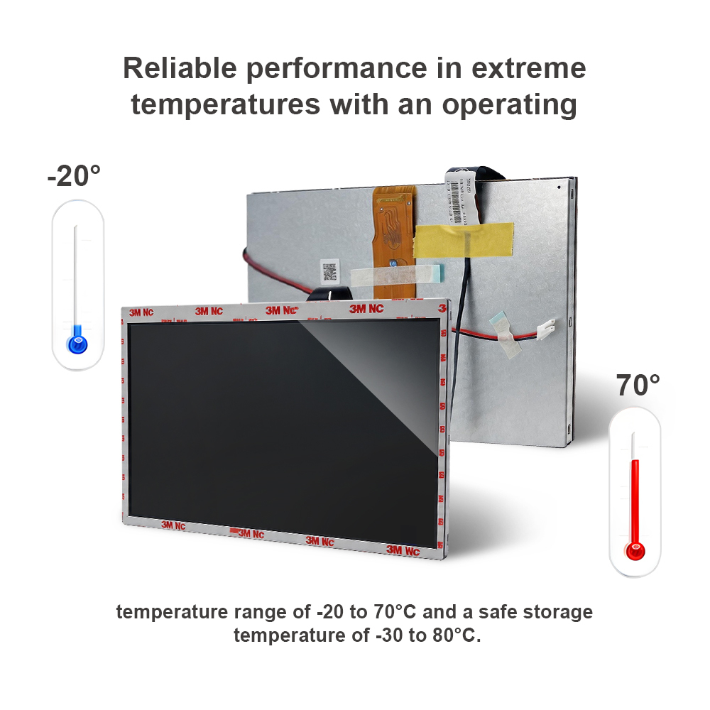
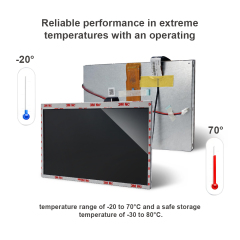
It is rated for −20 °C to 70 °C in operation, with storage from −30 °C to 80 °C. Treat those as ambient conditions around the module: inside a sealed cabinet in direct sun the air behind the glass can run hotter than the outside temperature, so leave some thermal headroom rather than sizing the enclosure to the limit.
Q2. How does the module keep touch accurate as the enclosure heats up?
The controller recalibrates its baseline continuously and switches between stored parameter sets as temperature rises, so there is no field adjustment to make. If you see drift after installation, check the mounting and the grounding first — a bezel that loads the glass unevenly, or a housing without a proper earth, causes far more trouble than heat once the module has been calibrated.
Q3. Can the module be used under long-term sunlight?
Yes. The cover glass, its coating, the printed border and the optical adhesive are all UV-resistant rather than indoor-grade, which is what keeps the front from going yellow and the border from fading across a long service life.
Q4. How is readability handled under strong sunlight?
The touch panel is fully bonded to the display, so there is no air gap to create a second reflection, and the cover glass carries an anti-reflection layer. That combination is what keeps contrast up in direct sun; the effect is easiest to see at an angle, where an unbonded panel normally turns into a mirror.
Q5. What protection does it have for outdoor use?
The front is built as a sealed structure for outdoor and industrial housings, with waterproof and dustproof design part of the construction. How much ingress protection the finished equipment achieves depends on your gasket, housing and assembly, so if the project carries a formal IP requirement, tell us the target at the design stage and we will confirm what the module can support.
Q6. How should the front surface be cleaned?
A soft cloth and mild soapy water are enough. Skip abrasive pads, scouring powder and solvent or ammonia-based cleaners — they attack the anti-fouling and anti-reflection coatings, and once those are worn the glass is harder to keep clear and more prone to glare.